by Frank Barrett
3rd Edition 9/21/2016
Abstract: There are two phases to the polar alignment problem. First, one must quantify the alignment error for each axis. Once alignment error is known, the mount must be adjusted to correct for this error. Often the adjustment amount must be estimated based on the magnitude of the error. This is primarily due to the fact that most mount manufacturers do not provide or calibrate the altitude and azimuth axes with high precision scales. This article will show a simple method utilizing a calculated star offset position to make the mount adjustment. The star offset position is calculated based on the known celestial coordinates of a reference star and the alignment error such that pointing the telescope at this coordinate and adjusting the mount to recenter the reference star will bring the mount into close alignment. This method is called “star offset positioning” and can greatly reduce the amount of time to perform the alignment procedure.
In Measuring Polar Axis Alignment Error [1] we discussed various methods to measure the polar alignment error. If the mount were designed with encoders on the altitude and azimuth adjustment axes, or if these were calibrated with an accurate visual scale, the adjustment to the mount would be fairly straightforward. Apparently mount manufacturers cannot justify the cost of such solutions and as a result many resort to simply estimating the adjustment amount. This inevitably results in multiple iterations of the measure and correct process. This consumes precious time and can be very error prone due to poor estimates and over correction.
It would be expedient if we could discover a way to adjust the mount more precisely so that the procedure would converge in a timely fashion. One simple solution would be to fashion high precision scales for both the altitude and azimuth axes. Another method, which will be discussed here, is to use one of the billions of reference points in the sky we call stars, as a means to make the adjustment. If we can translate the alignment error into an offset from a star’s celestial coordinates, then pointing the telescope to this offset position and recentering the reference star (by means of adjusting the mount) should bring the mount into very close alignment. Figure 1 illustrates this method.
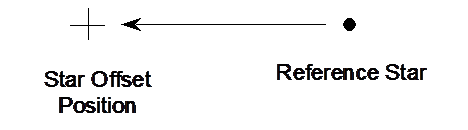
Figure 1. By calculating the appropriate
star offset position, we can make a precise alignment correction by recentering
the star via the mount’s altitude or azimuth adjustment mechanism.
The only remaining factor to determine is how to use the alignment errors to calculate the star offset position. To do this we will look at the azimuth and altitude axes independently and derive the appropriate equations.
When thinking about star offset positioning it is important to understand the angular distance a star moves as the mount is adjusted. For instance, when adjusting the mount in azimuth, the axis of rotation is about the zenith (assuming the mount base is level). This means that stars near the zenith will move a smaller angular distance than stars near the horizon for the same amount of azimuth adjustment. Figure 2 may clarify this.

Figure 2. Adjusting the mount’s azimuth
causes rotation centered on the zenith.
Stars near the zenith move a smaller angular distance than stars near
the horizon.
Although these angular distances vary based on altitude, it is important to understand that they all result in the same angular movement of the azimuth adjustment on the mount. Previous editions of this paper failed to take this into account and resulted in much over-thinking of the problem. What we can observe, however, is that corrections for azimuth will be more precise near the horizon due to the larger angular motion.
All that is necessary is to calculate the new equatorial
coordinates after shifting the reference star in azimuth. To do so we must first calculate the
reference star’s horizon coordinates: altitude and azimuth. We then adjust the derived azimuth coordinate
based on ![]() . Convert these
horizon coordinates back to equatorial coordinates and we have the offset
position desired. The interested reader
is referred to Meeus [2] for the mathematical details involved in the
coordinate transformations.
. Convert these
horizon coordinates back to equatorial coordinates and we have the offset
position desired. The interested reader
is referred to Meeus [2] for the mathematical details involved in the
coordinate transformations.
(Alt, Az) = EquatorialToHorizon(![]() ,
,![]() )
)
Az = Az + ![]()
(![]() ,
,![]() ) = HorizonToEquatorial(Alt, Az) (1)
) = HorizonToEquatorial(Alt, Az) (1)
Where:
![]() is the known
right ascension coordinate of the reference star
is the known
right ascension coordinate of the reference star
![]() is the known
declination coordinate of the reference star
is the known
declination coordinate of the reference star
Alt is the computed, instantaneous altitude of the reference star
Az is the computed, instantaneous azimuth of the reference star
![]() is the measured
azimuth error
is the measured
azimuth error
![]() is the computed
offset right ascension coordinate
is the computed
offset right ascension coordinate
![]() is the computed
offset declination coordinate
is the computed
offset declination coordinate
To correct your mount in azimuth, follow these steps:
When looking at the altitude adjustment, we observe from Figure 3 that the rotational axis is along the horizon in an east to west direction. As such, angular distances near the eastern or western horizon will be smaller than those near the meridian. The best place to make an altitude adjustment by means of star offset position is on the meridian, as this is where the largest angular distance is realized. Again, larger angular distances will ensure precision when making the adjustment.
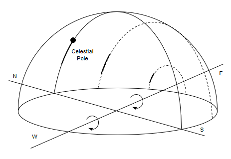
Figure 3. Adjusting the mount’s
altitude causes rotation centered on the east-to-west axis. Stars near the eastern or western horizon
move a smaller angular distance than stars near the meridian.
Previous editions of this paper limited altitude correction to the meridian. As discussed, that is the most precise location to make the correction, but we can provide the means to select stars away from the meridian for convenience or in the case of special needs.
What we are trying to do here is to calculate the position
of the reference star after it has been rotated by ![]() along the east/west
rotational axis. We already have the
math to accomplish this rotation in [2]. Think about it, whenever we transform
from horizon to equatorial coordinates or vice versa, we are shifting the axis
of rotation from (or to) the zenith to (or from) the celestial pole related to
an angle defined by the observer’s latitude.
If, instead, we generalize these equations to allow for an arbitrary
amount of rotation, the problem can be easily solved. First we convert from equatorial coordinates
to horizon coordinates, but instead of specifying the latitude we specify (latitude
-
along the east/west
rotational axis. We already have the
math to accomplish this rotation in [2]. Think about it, whenever we transform
from horizon to equatorial coordinates or vice versa, we are shifting the axis
of rotation from (or to) the zenith to (or from) the celestial pole related to
an angle defined by the observer’s latitude.
If, instead, we generalize these equations to allow for an arbitrary
amount of rotation, the problem can be easily solved. First we convert from equatorial coordinates
to horizon coordinates, but instead of specifying the latitude we specify (latitude
- ![]() ). This will result in
the correction we desire. Convert those
coordinates back to equatorial coordinates and we have the offset location
desired.
). This will result in
the correction we desire. Convert those
coordinates back to equatorial coordinates and we have the offset location
desired.
(Alt, Az) = EquatorialToHorizonArbitrary(latitutde-![]() ,
,![]() ,
,![]() )
)
(![]() ,
,![]() ) = HorizonToEquatorial(Alt, Az) (2)
) = HorizonToEquatorial(Alt, Az) (2)
Where:
latitude is the observer’s latitude
![]() is the known
right ascension coordinate of the reference star
is the known
right ascension coordinate of the reference star
![]() is the known
declination coordinate of the reference star
is the known
declination coordinate of the reference star
Alt is the
computed, instantaneous altitude of the reference star shifted by ![]()
Az is the
computed, instantaneous azimuth of the reference star shifted by ![]()
![]() is the measured
altitude error
is the measured
altitude error
![]() is the computed
offset right ascension coordinate
is the computed
offset right ascension coordinate
![]() is the computed
offset declination coordinate
is the computed
offset declination coordinate
To correct your mount in altitude, follow these steps:
There are many ways to measure the polar axis error. Some techniques measure each axis independently, while others can measure the error of both axes at once. When measuring and correcting each axis independently, it is usually expedient to correct the azimuth axis first before moving on to the altitude axis. Due to the spherical geometry it is oftentimes difficult to measure altitude error at the optimal location. This is discussed in [1]. Further, unless the mount is perfectly level it is important to measure each axis again to ensure that correction in one axis does not introduce a small error into the other axis.
In the case you are able to measure both axes errors in a single measurement, you have the choice to correct each axis independently or to correct both at the same time. Simultaneous correction can be done by calculating the offset coordinate for one axis and then using that result to calculate the offset coordinate for the other axis. The resulting offset coordinate will then correct both axes simultaneously.
However, when doing a simultaneous correction of both axes, it will be necessary to choose the reference star carefully. In this case, it will be necessary to choose a reference star on the meridian. Here’s why. Only on the meridian will an adjustment in the altitude axis result in a star’s apparent motion in an altitude-only direction. Once you deviate from the meridian, the star’s motion will appear to move in both altitude and azimuth. In the worst case, pointing directly either east or west, a movement in the attitude axis will cause the star’s apparent motion to be purely in azimuth (assuming a small motion) and will be parallel to the horizon. Because of this, it will be ambiguous to know how much of an azimuth adjustment is needed for the azimuth error versus the altitude error. A choice of star on, or very near the meridian, will remove this ambiguity and result in a more accurate correction.
All gears contain some amount of backlash. Backlash is the gear play encountered when meshed gears change rotational direction. There is some amount of gap between the gears that results in a temporary lack of movement of the meshed gear. Backlash is present in your mount as well. This is generally not a problem for the right ascension gears since the mount is always tracking westward and the backlash is taken up as a result. However, when moving in declination backlash can be problematic. Especially in the case of the star offset positioning, declination backlash can affect the precision of the correction.
There is a simple technique to overcome this shortcoming. When positioning the mount at the reference star take note of the direction from the reference star to the calculated offset position. If the direction is northward, finish the centering operation towards the north. Likewise, if the direction is southward, finish towards the south. This will take out the declination backlash and the move to the offset position will be performed with the best precision your mount can provide.
A simple method for adjusting for polar alignment error has been given. By selecting a reference star close to the meridian and celestial equator, a star offset position can be calculated from the altitude and azimuth alignment errors. Pointing a telescope at this position and adjusting the mount to recenter the reference star brings the mount into very close alignment. The procedure takes only a few minutes and can dramatically reduce the time required to polar align the mount while at the same time increasing the accuracy of the process. A clear win-win scenario!
[1] Barrett, F.A., Measuring Polar Axis Alignment Error, (2016)
http://celestialwonders.com/articles/polaralignment/MeasuringAlignmentError.html
[2] Meeus, J., Astronomical Algorithms, 2nd Edition, (1998)